
With the advent and growing popularity of EV’s, manufacturers have been working to electrify the various smaller systems that used to be powered by the internal combustion engine — systems like steering, HVAC, and brakes. All of these used to be powered by engine-driven pumps, compressors, and manifold vacuum. Without a traditional engine, or an engine that is always on, OEMs and suppliers have had to find alternative ways to power these systems, and with a massive battery onboard, it makes sense to make everything electrically powered.
In the case of steering, this has resulted in an electric motor driving the rack. Of course, even in non-EV’s or hybrid vehicles, electric steering has taken over due to their higher overall efficiency. In the case of HVAC, it meant an electric motor (and not a gas motor’s accessory drive) driving the AC compressor. In the case of brakes, it has also resulted in an electric motor replacing the old vacuum booster, but there is an added complication that makes braking systems a bit more difficult to electrify.
It’s All About Energy
Braking systems at their fundamental core are really just energy conversion devices. When a car is moving, it has a certain amount of energy which is equal to ½ the vehicle mass times the velocity squared. It’s called Kinetic Energy and every object that is in motion has it.
Kinetic Energy = 1/2 x Mass x Velocity²
In order to bring an object to a stop, you first have to get rid of this kinetic energy. That’s where brakes come in. When you step on the brake pedal, the brake pads make contact with the brake rotors (or drums), and the resulting friction creates heat which is then dissipated to the surrounding air. Heat is another form of energy, so what your brakes are doing is converting the energy of motion, i.e. the kinetic energy, into heat energy. Since kinetic energy is directly related to vehicle speed, as the speed reduces, so does the kinetic energy. In the same way, as the kinetic energy is reduced (by conversion to heat), the speed must also reduce.
Regeneration
The downside here is that standard brakes turn kinetic energy into heat which is then dissipated to the air. All the energy that was used to bring the car up to speed is now lost to the air when you slow down. This is where one of the big advantages of EVs comes in. EVs (and hybrids, too) have the ability to take the electric motor that drives the wheels and temporarily turn it into a generator, which then partially recharges the battery. It’s called regeneration. By doing this, the kinetic energy is not just lost to the air, but is instead turned into electricity and put back into the battery so it can be used again later. This is the fundamental reason why hybrids get better fuel economy than their non-hybrid cousins. Energy that would normally be lost is instead recovered so it can be used again later.
But just as there is a limit to the amount of power an electric motor can provide during acceleration, there is a limit to the amount of power it can generate during deceleration. And this limit is normally well below the capabilities of a normal brake system. Take for example a 2000 Kg car slowing down at 0.8G, which is well within the abilities of most modern brakes. The brakes in this case have to be able to provide on the order of 4000 lb-ft of torque to the 4 wheels. That’s a LOT of torque, but that is perfectly normal for a modern brake system. There are some EV’s out there today that have motors that can deliver that kind of power, but in general, most deliver much less, so it is not possible for them to slow the car down the way the regular brakes would. Also, unless the EV has hub motors, there will not be individual wheel control under regeneration, so there is still a need for standard brakes. On top of that, the electrical energy that is being generated needs to go somewhere. Most batteries cannot recharge at the same rate as they can discharge, so there is a limit to how much energy can flow into the battery. All this means is that we can’t just rely on regeneration to stop the car. We need to combine regeneration and normal hydraulic brakes to get the job done.
But this presents an issue. When you step on the brake pedal, something needs to decide how much of the braking power is going to come from regeneration and how much will come from hydraulic braking. And this decision needs to be made in a way that is transparent to the driver. When you step on the brake pedal, it should feel like an ordinary brake system. You don’t want the pedal feel to change depending on how much braking is done by regeneration vs. hydraulics. It should always feel the same.
In the past, this “blending” of regen and hydraulics was either done mechanically or not at all. Some hybrids used a mechanical system that used a slotted connection between the pedal and the brake booster input rod. As the brake pedal was pushed, a pin would move within the slot and a position sensor would tell the brake module how far the driver was pushing the pedal and how much regen braking was required. The pedal would also push against a spring and/or rubber pucks that were designed to simulate the feel of a normal pedal. Once the pin bottomed out in the slot, the pedal would be pushing directly on the brake booster similar to a standard system, and hydraulic pressure would be sent to the brakes calipers.
Many of these systems had a slight artificial feel to them and the transition between regen braking and hydraulic braking was fairly evident. The pedal feel wasn’t consistent.
The other method was to ignore the problem altogether and put all the regen on the accelerator pedal. Lift off the accelerator and the motor would go into regen and slow the car down. It gave birth to the concept of one-pedal driving where, if you planned ahead enough, you could drive solely with the accelerator and rarely, if ever, touch the brake pedal. The only thing the brake pedal did in these cars was operate the hydraulic brake system. Tesla was the first (to my knowledge) to use this system, and it meant the brake system did not need any fancy EV specific software or hardware.
The problem was that these systems could not utilize the regeneration capability of the motors to their fullest extent since the amount of deceleration this would give was felt to be too much for smooth driving. You would have to be much too careful with your accelerator pedal movements to avoid a jerky ride. In Tesla’s case this meant limiting regen braking to 0.15G. BMW later increased this to 0.2G with the i3.
A Better Way
But what if there was a brake system that allowed the fullest use of regen, could blend regen and hydraulic brakes seamlessly, not give a jerky ride, and even give the driver a choice of one-pedal driving or something more like the old car he/she was used to where lifting off only gave a little bit of engine braking? Enter the new de-coupled braking systems.
Notice my use of the term “de-coupled” instead of “brake-by-wire.” This is purely intentional and it will become clear later why I say this.
In a standard modern hydraulic braking system, when you press on the brake pedal, it pushes a rod into the master cylinder which sends hydraulic fluid under pressure via the anti-lock brake module out to the brake calipers located at the four wheels.
In a de-coupled system, the brake pedal still pushes a rod into the master cylinder, but now instead of sending hydraulic fluid under pressure to each of the four wheels, the pressure is sent to a “pedal simulator” consisting in many cases of a spring and rubber puck. The hydraulic pressure tries to compress the spring and rubber puck, and the stiffness and shape of the spring and rubber puck give the impression that you are pressing against a normal brake system. At the same time, pressure and position sensors tell the system how hard the driver is pressing on the pedal.
While this is happening, a computer looks at the data coming from the sensors and decides if the desired braking can be accomplished using regeneration or if hydraulic braking is necessary. If regeneration is sufficient to provide enough braking, then the computer will send a signal to the powertrain controller, telling it to start the regeneration process. If, on the other hand, hydraulic brakes are required, the computer will send a signal to a motor housed in the brake booster, which pushes a rod into another smaller master cylinder. This secondary master cylinder is what now sends hydraulic fluid under pressure out to the four wheels via the anti-lock brake module.
In this way, a computer is able to decide how much regeneration is going to be used and how much hydraulic pressure is going to be used to slow the car down while all the time, the driver is simply pushing against a simulator that feels like a normal brake pedal. The driver is blissfully unaware of the decisions this computer is making and just feels the car slowing down in response to their pedal input.
But what would happen if this computer were to fail, or if power to the brake booster were cut for some reason and there was no power available to run this little motor inside the booster? There would be no way to create the hydraulic pressure needed to stop the car.
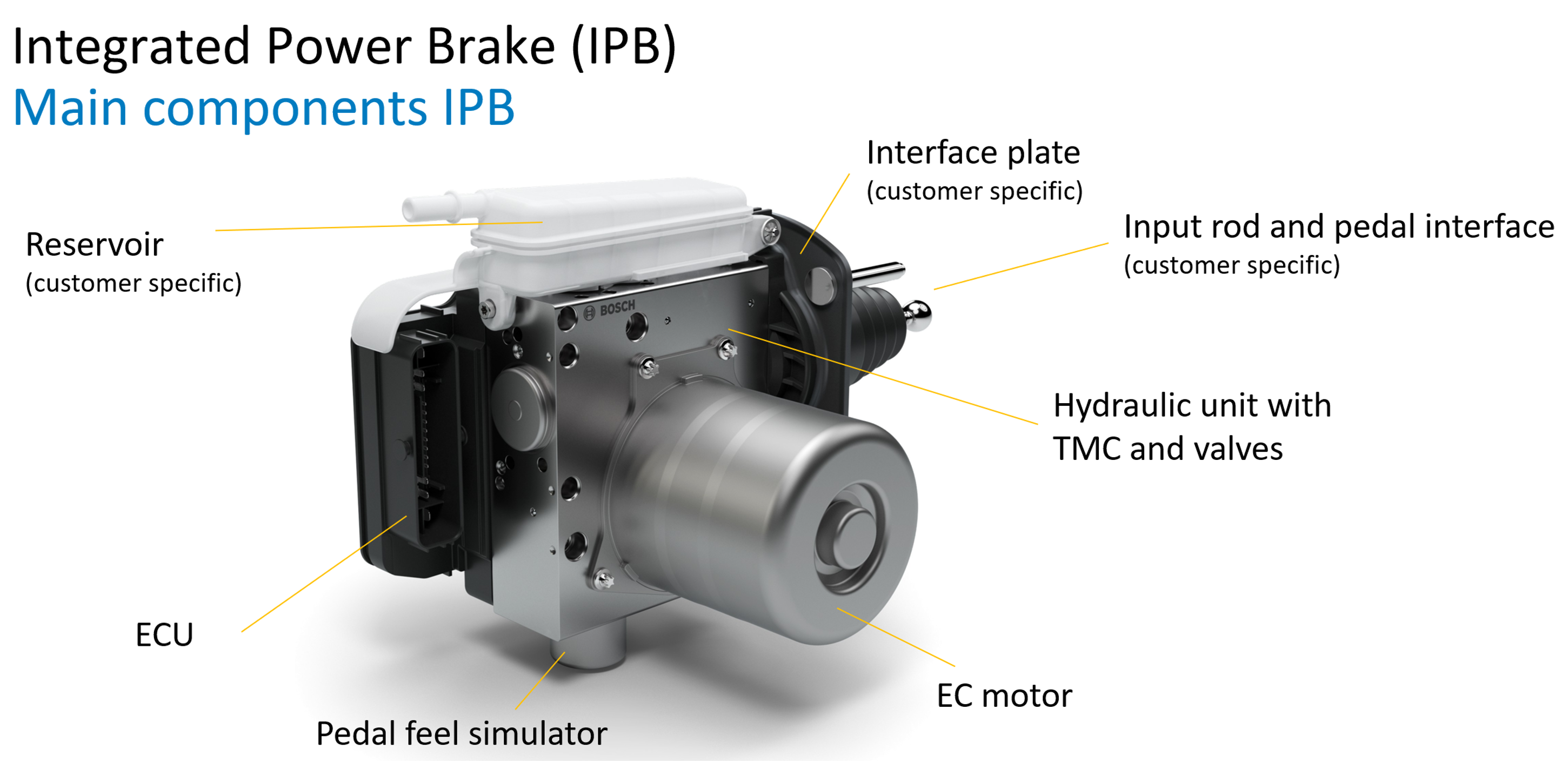
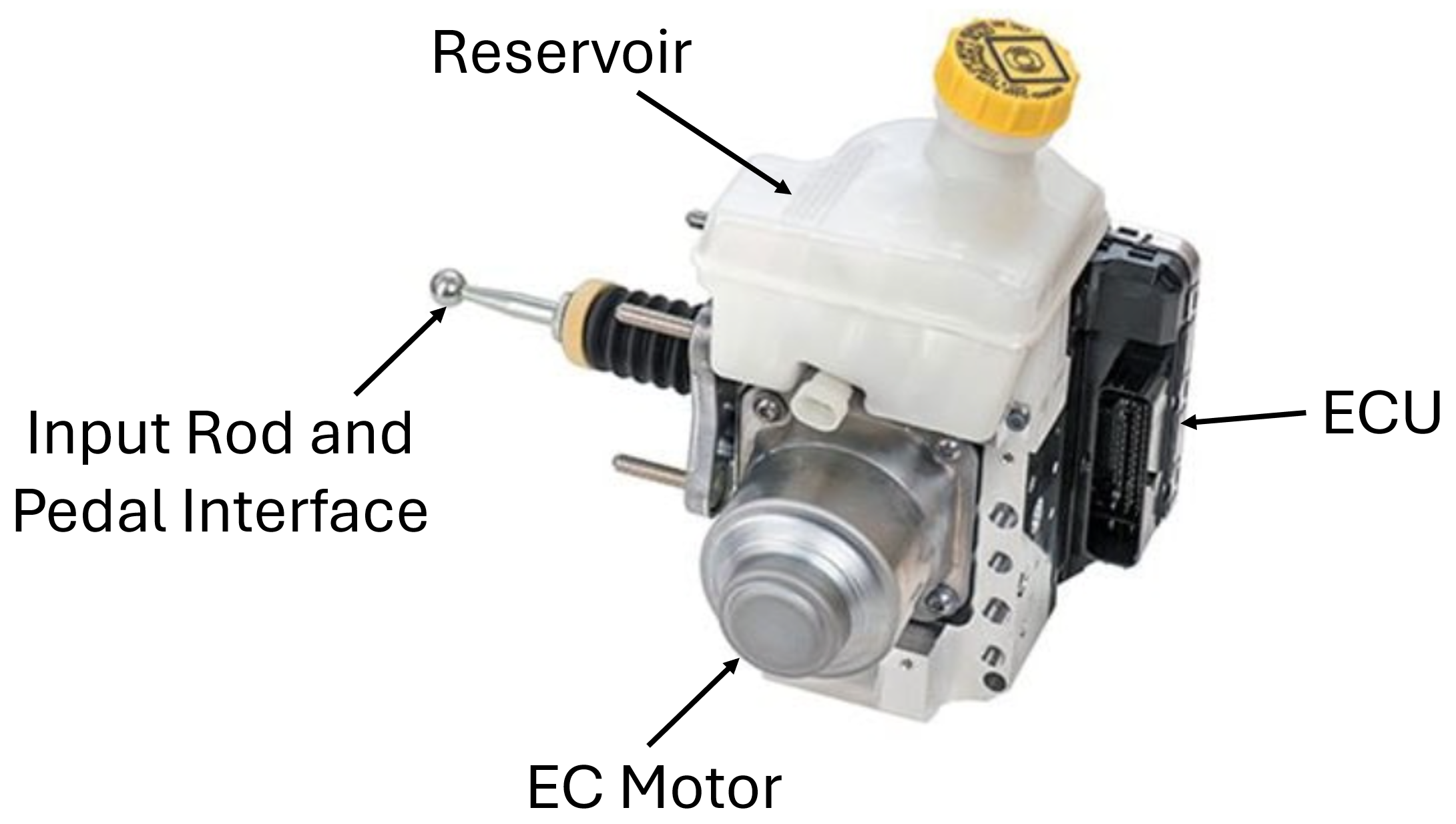
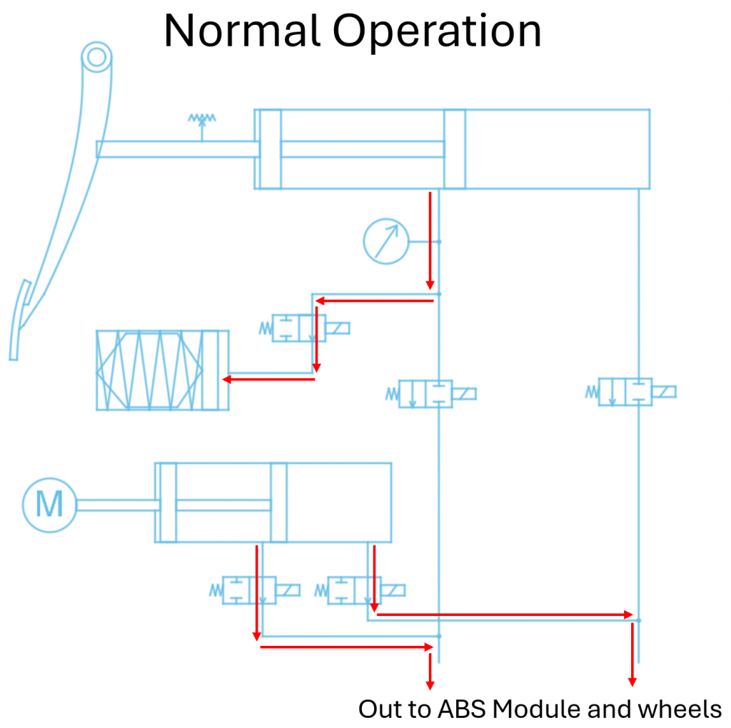
Fortunately, this has been taken into account in the design of the booster. Here is a diagram of what a typical de-coupled system looks like:
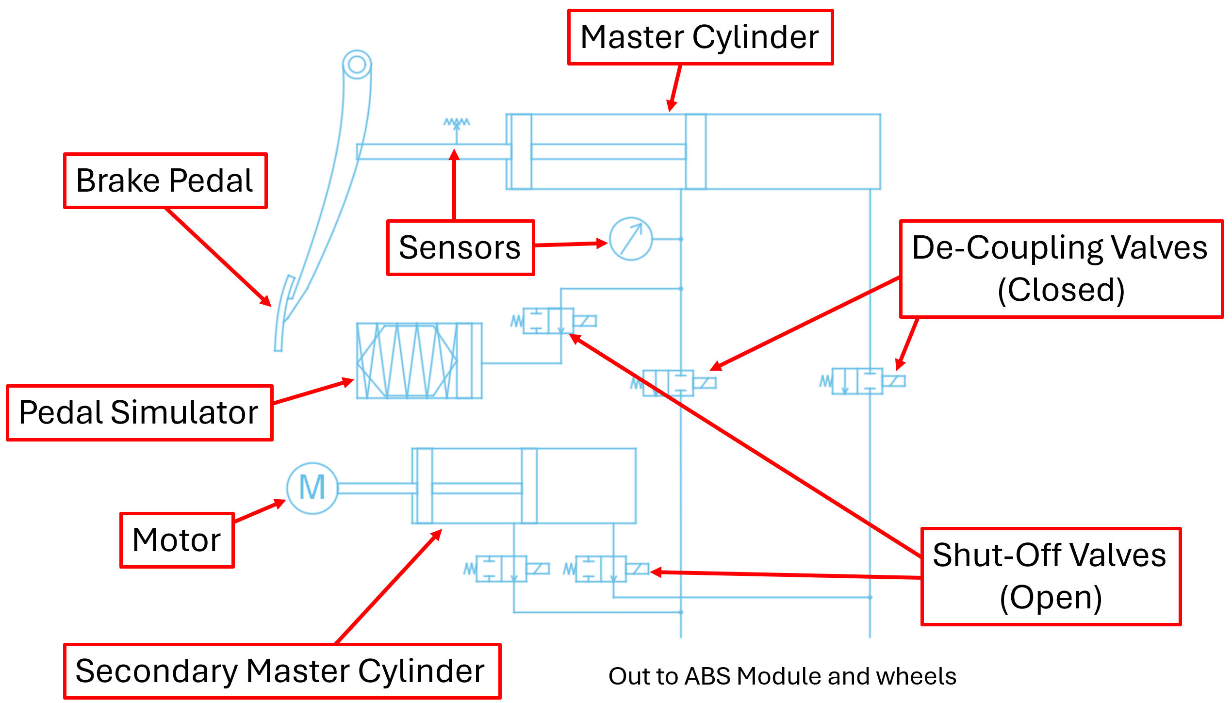
You can see how the pedal is attached to a regular-looking master cylinder and how the pressure from this cylinder goes to the pedal simulator. You can also see the extra motor and its smaller master cylinder and the lines going from there out to the anti-lock brake module and to the wheels. But there are a few extra parts in there as well. These are valves, which control how the hydraulic fluid will flow inside the booster. Two in particular are of interest to us and they are labeled “de-coupling valves” in the diagram above. These valves are normally open, meaning that when they are not powered, they are in an open position. Conversely, the other two valves, which lead out from the smaller master cylinder, are normally closed.
Under normal operating conditions, when the car is powered up, the de-coupling valves will receive power and will close, preventing hydraulic pressure coming from the main master cylinder from flowing out the anti-lock brake module and the four wheels. Instead, this pressure is forced to flow to the pedal simulator. The other two valves which are normally closed, will now be open, and hydraulic fluid will flow from the secondary master cylinder out to the wheels.
But if there were to be a power failure, or if the computer that controls these valves were to stop working, the springs inside the de-coupling valves would automatically open them up again, and the springs inside the other two valves would automatically close them again.

Under these conditions, fluid would be allowed to flow directly from the main master cylinder out to the four wheels, and the whole system would act like a traditional hydraulic brake system.

In this way, there can never be a situation where an electrical failure would prevent the driver from stopping the vehicle.
Terminology
These diagrams also show why brake engineers prefer to call them “de-coupled” rather than “brake by wire.” Under normal conditions, the hydraulic circuit attached to the brake pedal and the hydraulic circuit flowing out to the wheels are de-coupled from each other. While it is true that under these conditions, the only thing connecting the two circuits is a wire going to a computer, the term “de-coupled” more accurately describes what is going on here. It also reserves the term “brake by wire” for future systems that eliminate the use of hydraulics altogether and have only wires (not hydraulic lines) connecting between the brake pedal and the calipers at each wheel. These systems would use a motor at each caliper to actuate the brakes in response to a signal coming from sensors attached to the brake pedal. There would be no hydraulics in such a system at all. This doesn’t yet exist in any form other than experimental, but I can see a future where they get introduced and slowly take over from the hydraulic systems we know today.
Regulation
There is one more aspect of the brake booster that is impacted by the use of a de-coupled brake system. Brakes are some of the most heavily regulated systems in your vehicle. In the U.S, the regulation that governs brakes is called Federal Motor Vehicle Safety Standard 135 (FMVSS 135). In Canada it is CMVSS 135, and in Europe and most of the rest of the world it is the United Nations Economic Commission for Europe regulation R13H (ECE R13H). These regulations cover a multitude of topics starting with the fact that brake systems need to have a backup (which has led to the split braking systems all vehicles have — i.e. two wheels are on one hydraulic system, two wheels are on another separate one), to the conditions the brake lights must come on, and even to the text that must be displayed on the brake reservoir cap and how easily you must be able to see the fluid level in the reservoir. In FMVSS and CMVSS 135, there is also a requirement for the performance of a braking system that has lost power, either through a loss of vacuum in the case of a vacuum-boosted system, or electrical power in the case of an electrically powered system.
If the system that provides power to the brake booster fails, the car must be able to stop from 100 km/h in no more than 551 feet (yeah, there is a weird mix of units here but that’s how it’s written!) while needing a brake pedal effort of no more than 500 N (112 lbs.).
So, what does this mean for our braking system? If our brake system only had to meet the above regulation, it would be fairly easy to design a master cylinder and four calipers to do it. We would choose a relatively small bore master cylinder and use large-diameter pistons at each caliper. That way, for every lb. of pedal force, we would generate a lot of hydraulic pressure, and for each PSI of hydraulic pressure, the pistons in each brake caliper would generate a lot of force against the brake pads. Easy peasy!
Unfortunately, the same master cylinder and brake calipers also need to stop our car from max speed when everything is working correctly. If we used a small bore master cylinder and large diameter pistons in the calipers, we would get a lot of pedal travel. That might be fine for a failed boost emergency situation where all you care about is stopping the car safely, but it’s not fine when everything is working correctly. We don’t want a lot of pedal travel under normal conditions because that would mean our pedal would need to start out very high and it would be uncomfortable to have to move our foot so much. And so, we end up with master cylinders that are a little larger than we would ideally want and caliper pistons that are a little smaller than we would ideally want.
There is one more complication we need to consider here as well, and that is that we need to be able to stop our car when one of our hydraulic circuits has failed. If you’ve ever had a failure of a hydraulic circuit, you will have experienced the problem here, which is that the brake pedal will first move a lot before you get any braking action. This is because the master cylinder cannot build pressure in the remaining good circuit before the bad circuit has bottomed out. This means even more pedal travel has to be accommodated for.
The bottom line here is that we cannot simply use a small bore master cylinder to meet the failed booster requirement. We have to design our system to meet ALL of the requirements and the result is by definition a compromise. Obviously, it is possible since every car out there does it, so it’s not really that big a deal. But, these new de-coupled systems give us a benefit in this regard that is not immediately obvious.
Since the master cylinder is normally only connected to the pedal feel simulator, we can make it any diameter we want. We can design the simulator so that a small diameter master cylinder doesn’t result in long pedal travels. And, since the caliper pistons are normally only connected to the secondary master cylinder, we can make them any diameter we want as well. Large caliper pistons just mean more travel for the secondary master cylinder and motor, but that will have no impact on our pedal travel. When there is a failure in the system and the de-coupling valves open up, we will then have a small-diameter master cylinder pushing fluid into large-diameter caliper pistons. Yes, it will lead to long pedal travel, but at that point, you are only really concerned about stopping the car safely. Pedal travel will be longer, but pedal effort will be lower.
All in all, these new de-coupled brake systems provide some very important, and tangible benefits and when things do go wrong, they can be designed to be even safer than a traditional system.